Cookies and analytics.
We use analytics tools to see which pages are read and which companies visit this website. They set cookies only if you agree. The website works without them. Details in our privacy policy.

Software
From scan to decision.
BliXray develops the software that turns X-ray images into an inspection result: scan control, 3D reconstruction, image optimisation with AI and automatic evaluation. Each algorithm is adapted to the part it has to judge.
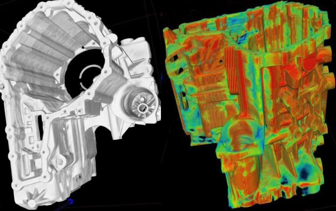
A CT system takes thousands of X-ray images of one part. Software reconstructs them into a 3D volume, finds the features that matter and decides whether the part passes. This step sets how fast, how reliable and how automatic an inspection can be.
Capabilities
The software controls source, detector and axes and stores an inspection programme per part. For printed circuit boards, programmes are created from CAD data instead of manual teaching.
On inline systems, reconstruction starts while the scan is still running. Artefact-suppression algorithms clean the volume before it is evaluated.
AI-based image optimisation sharpens the features the evaluation depends on. Scatter and artefact removal makes thin walls and inner channels detectable automatically.
Defects are located, classified and judged automatically, with a pass or fail result per part. Defect types and limits are configured to your inspection standard.
Wall thickness and deviation from the CAD model are measured in the volume and shown as colour maps. CAD and PMI data drive the dimensional inspection; a scan can also become a CAD model.
Porosity is calculated as an area or volume rate and mapped to its position in the part. For composites and powders the software evaluates fibre direction and particle size.
A scanned assembly is split automatically into its labelled components. Position and alignment of each component are checked without disassembly.
Results are stored with a traceable record per part and exported to the MES. Defect statistics go back to the process step that causes the fault.
Defects of defined type, size and position are inserted digitally into images of your part. The labelled X-ray images train the inspection software before real defective parts exist. Real machine images remain the reference for final validation.
We start with the feature that has to be found and the decision that has to be made. Where a standard evaluation is not enough, we develop the algorithm for your part.
Which region is scanned, from which angles and how fast depends on what the software needs to see. Scanning only that region shortens the inspection.
Source, detector, mechanics and shielding follow the scan strategy. This is how software development leads to new BliXray machines and cabinets.
Yes. Defect types, limits and evaluation are configured per part. Where a standard evaluation is not enough, we develop the algorithm for your part.
Yes. Results are exported to the MES and stored with a traceable record per part.
It is in development. Talk to us if you have an inspection task without enough real defect images.