Application note ·
BliXray offers CT inspection for aerospace castings, welds and bonded joints
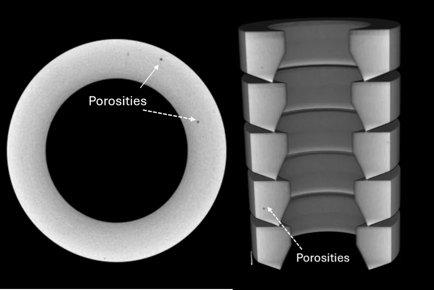
BliXray offers CT inspection for aerospace castings, from the wax pattern to the finished part, and for the welds and bonded joints that follow in engine and airframe work. A single BliXray Laboratory CT system checks wax patterns and ceramic shells before the pour, measures wall thickness against the CAD model and shows porosity, lack of fusion and bond-line voids without cutting the part.
BliXray addresses investment foundries, engine-assembly shops and airframe MRO and conversion facilities that are adding capacity for defence and civil aerospace programmes in Europe. Each of these stages produces its own non-destructive testing workload, and BliXray covers it with one computed tomography (CT) method and one data set per part. Typical inspection tasks are:
- internal cracks in wax patterns before the ceramic shell is built
- shell thickness, porosity and material distribution before the metal is poured
- wall thickness and deviation from the CAD model on cast and machined parts
- porosity, cracks, lack of fusion and lack of penetration in welds
- voids, delamination and incomplete adhesive coverage in bonded joints
Defects are caught before the metal is poured
Investment casting of turbine blades and structural parts runs through several stages, and each stage before the pour is a chance to stop a defect early. BliXray Laboratory CT scans the wax pattern and shows internal cracks before the ceramic shell is built around it. A crack left in the wax transfers into the shell and then into the casting. After shell building, a second scan checks that the shell thickness is uniform and reveals porosity, cracks and uneven material distribution in the ceramic.
The foundry therefore decides on rework while the part is still a wax pattern or a shell, not after a casting has failed final inspection. The same scan protects the accuracy of cooling channels and thin sections in the finished blade. “With CT on the wax pattern and the shell, a foundry moves the accept or reject decision upstream, to the point where rework is still cheap,” says Adrian de Riz, Managing Director of BliXray.
Wall thickness is measured against the CAD model
On a cast or machined blade, wall thickness and conformance to the CAD model are safety-critical checks. BliXray’s Laboratory CT analysis software measures wall thickness at defined critical spots and compares the full part automatically with its CAD model. Each measurement is checked against maximum and minimum thresholds. The result appears as a colour heat map that shows where the part deviates from nominal and where a wall is thinner than allowed.
The same metrology software provides coordinate measurement, regions of interest and nominal-to-actual comparison in several viewports. It covers turbine blades, machined parts and other dimensional checks such as distance measurement. Core shift and out-of-tolerance geometry become visible without sectioning the part, so the accept or reject decision follows directly from the scan.
Welds, bond lines and composites are inspected whole
Engine assembly and airframe conversion add a different task: welds, adhesive bond lines and composite structures that cannot be checked visually once assembled. BliXray Laboratory CT reveals porosity, cracks, lack of fusion and lack of penetration in welds without cutting the part. In bonded and glued joints it shows the internal adhesive distribution, voids, delamination and incomplete coverage at composite and multi-material interfaces.
The software calculates the bonded surface area and the coverage percentage automatically from the scan. In composite structures, CT detects metallic inclusions and foreign particles. In graphite parts it reveals internal porosity, which acts as a stress concentration in service. “An engine or airframe team gets traceable 3D data on every weld and bond line it scans, without taking the assembly apart,” says de Riz.
The scan data supports accept and reject decisions
For each stage, BliXray Laboratory CT delivers a result that a quality engineer can act on directly:
| Stage | Inspection task | Result from the CT data |
|---|---|---|
| Wax pattern | Internal cracks | Crack location in 2D slices and 3D view |
| Ceramic shell | Thickness uniformity, porosity, cracks, material distribution | Shell defects found before the pour |
| Cast or machined part | Wall thickness, CAD comparison, core shift | Colour heat map with maximum and minimum threshold checks |
| Welds | Porosity, cracks, lack of fusion, lack of penetration | Defect location without cutting the part |
| Bonded joints | Adhesive distribution, voids, delamination, coverage | Bonded area and coverage percentage, calculated automatically |
| Composites and graphite | Metallic inclusions, foreign particles, internal porosity | Inclusion and pore location in 3D |
In practice, BliXray starts with test scans of representative parts from each stage. The first scans set the reference for wax patterns, shells, castings and joints. Further scans are then compared with that reference and with the CAD model. More on CT for aerospace, castings and defence is on the BliXray website.
Test scans available
BliXray offers test scans of customer castings, welded and bonded parts on its Laboratory CT systems and through its CT testing service.
Contact: Adrian de Riz, Managing Director, BliXray Technologies GmbH
a.deriz@blix-ray.de · +49 1578 0477753 · www.blix-ray.de
About BliXray: BliXray Technologies GmbH, Hannover, designs and builds industrial CT systems and X-ray safety cabinets. Manufacturers in defence, aerospace and research use BliXray CT to inspect safety-critical parts without destroying them. BliXray cabinets and containers house X-ray sources up to 300 kV at a protection level of 0.5 µSv/h. CT for critical parts. Shielding for any source.